
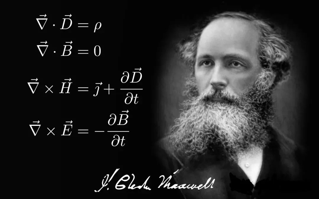
In 1873, British mathematician Maxwell summed up the equation of electromagnetic field – Maxwell equation. The equation shows that: electric charge can produce electric field, current can produce magnetic field, and the changing electric field can also produce magnetic field, and the changing magnetic field can produce electric field, which predicts the existence of electromagnetic wave.
Fourteen years later, in 1887, the German physicist Heinrich Hertz designed the first antenna to test the existence of electromagnetic waves. Wireless communication began in 1901 when the Italian physicist Gulimo Marconi used a large antenna to communicate over oceans.
The basic function of antenna: It is used to convert high-frequency current (or guided wave) energy into radio wave and transmit it to space according to predetermined distribution. When used for receiving, it converts radio wave energy from space into high frequency current (or guided wave) energy.
Therefore, the antenna can be considered as a guided wave and radiation wave conversion device, is an energy conversion device.
Antenna gain
An important characteristic of an antenna, independent of whether it is used for transmitting or receiving, is antenna gain.
Some antenna sources radiate energy equally in all directions, and this type of radiation is called isotropic radiation. It’s like the sun radiating energy in all directions. At a fixed distance, the solar energy measured at any Angle will be roughly the same. Therefore, the sun is considered to be an isotropic radiator.
All other antennas have the opposite gain to an isotropic radiator. Some antennas are directional, that is, more energy is transmitted in some directions than in others. The ratio between the energy propagating in these directions and the energy that the antenna does not propagate directionally is called the gain. When a transmitting antenna with a certain gain is used as a receiving antenna, it will also have the same receiving gain.
Antenna pattern
Most antennas emit more radiation in one direction than in the other, and radiation like this is called anisotropic radiation.
The directivity of antenna refers to the relation between the relative value of antenna radiation field and the spatial direction under the condition of the same distance in the far region. The far field strength of the antenna can be expressed as
Where, is the direction function, independent of distance and antenna current; Are azimuth Angle and pitch Angle respectively; Is the wave number and is the wavelength.
The directional function is represented graphically as the antenna’s directional graph. In order to facilitate the drawing of the plane, the general drawing of the two orthogonal main plane directions.
Antenna pattern is a graphical representation of the spatial distribution of antenna radiated energy. Depending on the application, antennas should only receive signals in one direction and not in others (e.g. TV antennas, radar antennas), on the other hand, car antennas should be able to receive signals from all possible transmitter directions.
The desired directivity is achieved through the targeted mechanical and electrical structure of the antenna. Directivity indicates the receiving or transmitting effect of an antenna in a certain direction.
Two different types of graphics can be used to plot antenna orientations – cartesian and polar coordinates. In a polar graph, the point is projected onto the coordinate plane along the axis of rotation (radius), and the polar graph of radiation is measured. As shown in the picture below.
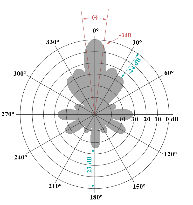
If the maximum value of the spatial orientation graph is equal to 1, the orientation graph is called the normalized orientation graph, and the corresponding orientation function is called the normalized orientation function. Emax is the electric field intensity in the direction of the maximum radiation, while is the electric field intensity in the direction of the same distance.
The direction diagram of the relationship between the power density and the direction of radiation is called the power direction diagram.
Post time: Feb-14-2023